Gallery details
This is less about “form” and more about perception through thresholds. You’re slicing color into contour, contour into group, group into structure—encoding difference as boundary. There’s a subconscious visual metaphor in that: about how we read, divide, or interpret information.
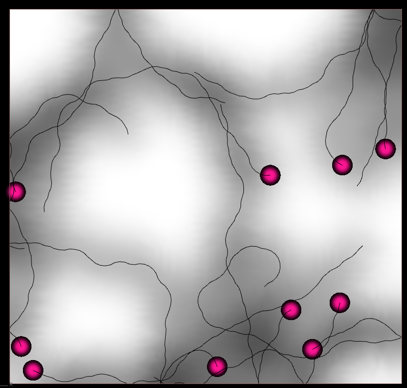
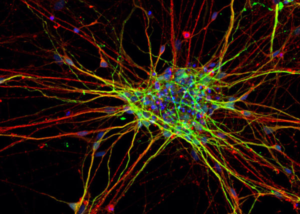
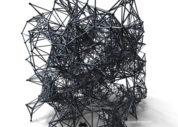
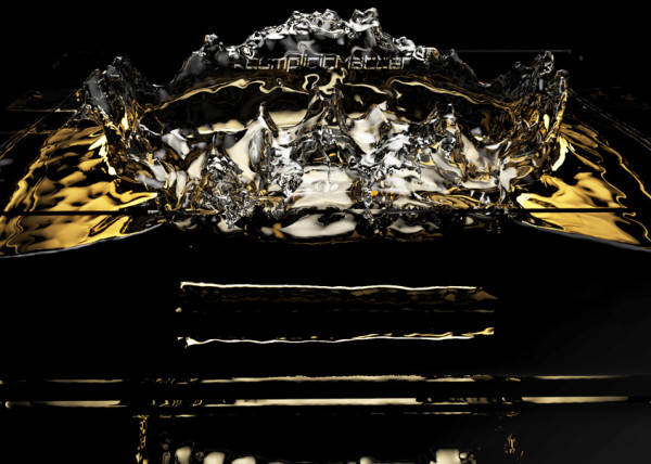
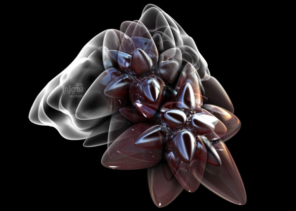
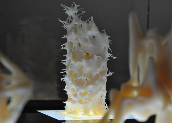
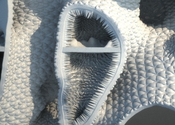
This implementation is based on the logic described in this algorithm [https://grgrdvrt.com/works/contour-lines/] for contour lines based on noise, in our case is from a color data mesh. I initially fell inlove with the iso-contouring by playing w/ ZBrush polygrouping & group loops functions. They produce extremely intricate groupings of meshes based on color thresholds as seen below. Obviously Z-Brush’s meshing capabilities are unmatched however I always wanted to attempt to generate a process that was similar.
ALGORITHM –
As described in the Grgrdvrt post the typical way to achieve a process like this is implementing a marching cubes algorithm, however
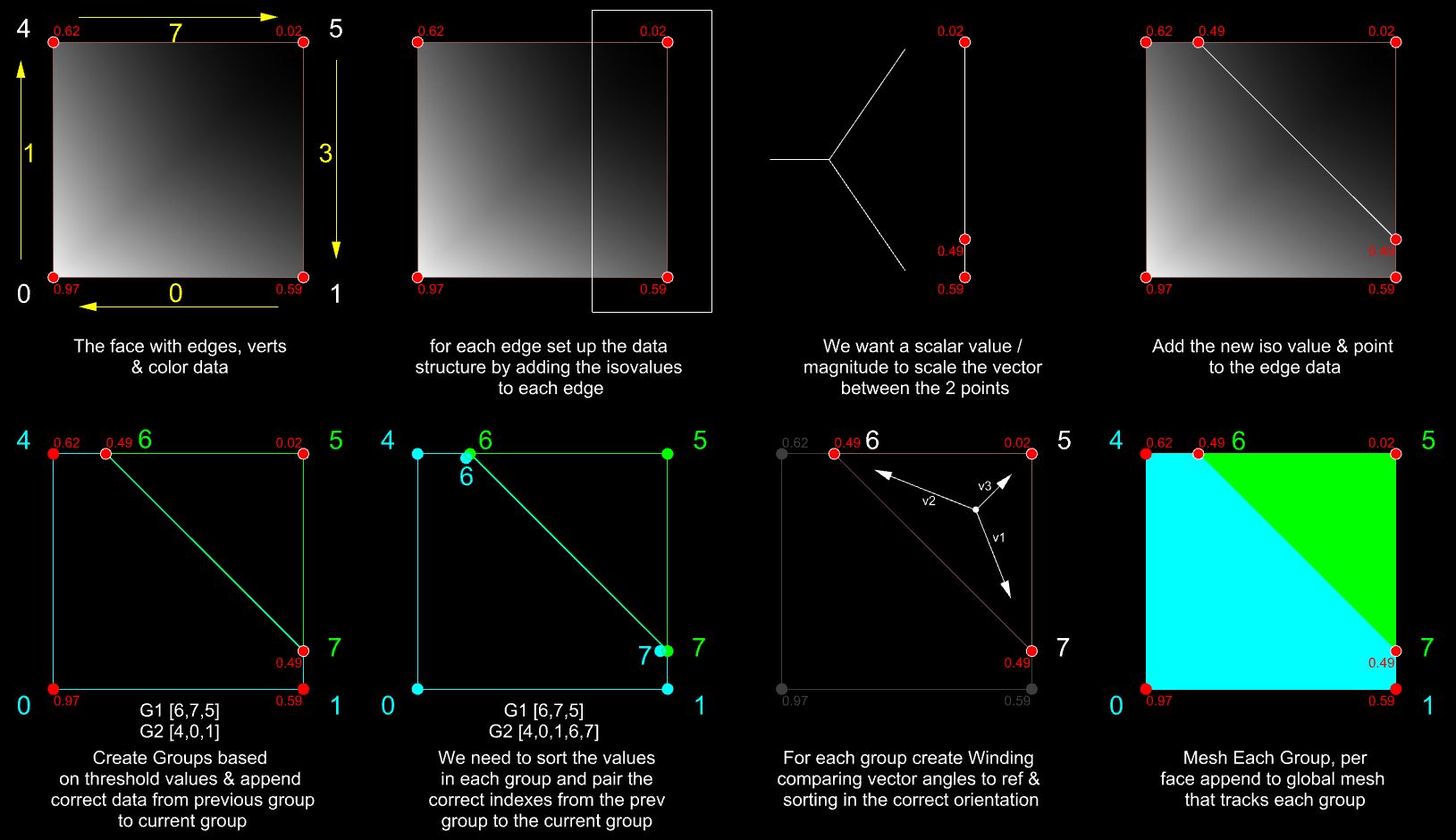
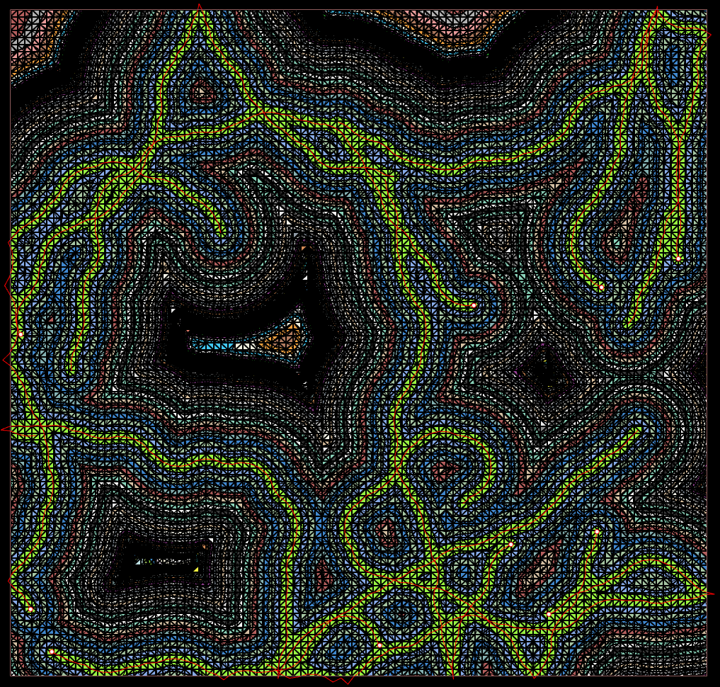
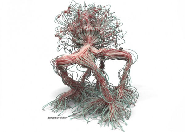
Groupings = Since we are interested in multiple iso-values at the same time (driven by the number of groupings the user wants) a better solution was needed in order to be able to create the mesh groupings that can near mirror the ZBrush groupings by polypaint. So instead of computing one iso-value per face, we will compute all the iso-values per face, add them to a list, create the winding, create a mesh and append it to the mesh created for each group. This will give us a continuous mesh loop around the entire global mesh, with each group containing a unique color.
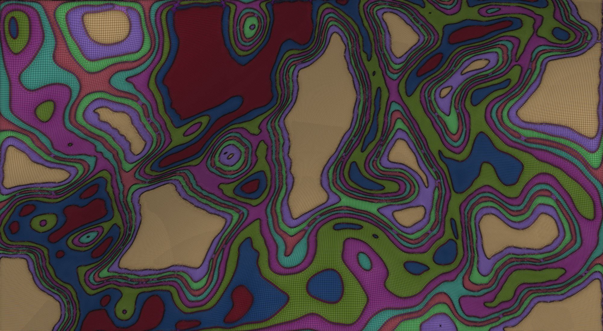
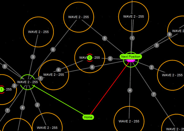
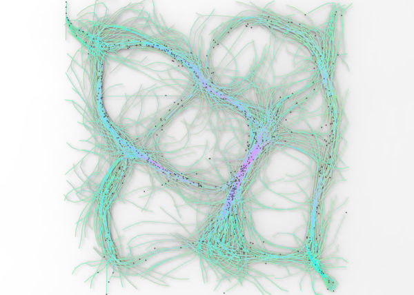
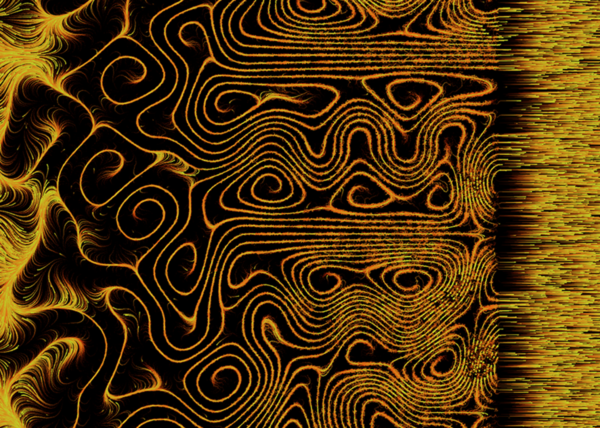
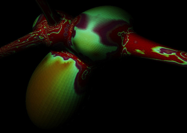
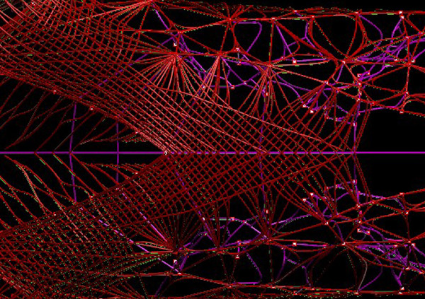
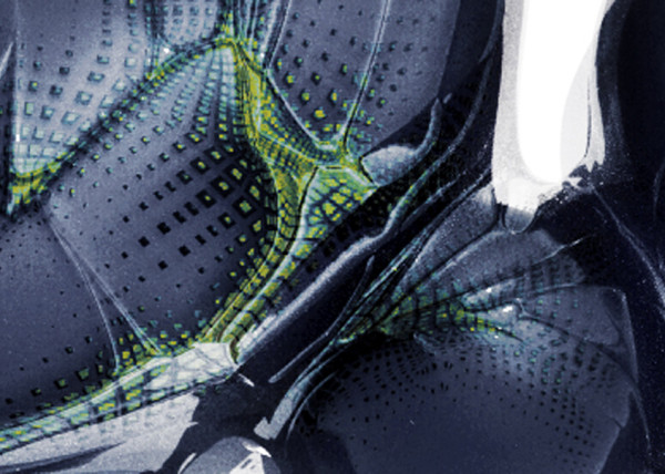
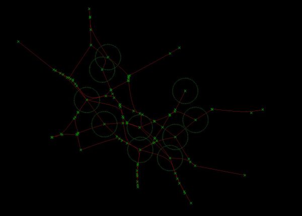
.EXAMPLE BELOW = This example is looking at simply 2 groups, Group 1 w. values between 0.0 – 0.5 and Group 2 w. values between 0.5 – 1.0. The Yellow represents topological face edge index, White represents topological face vertex index and the Red represents vertex color data.
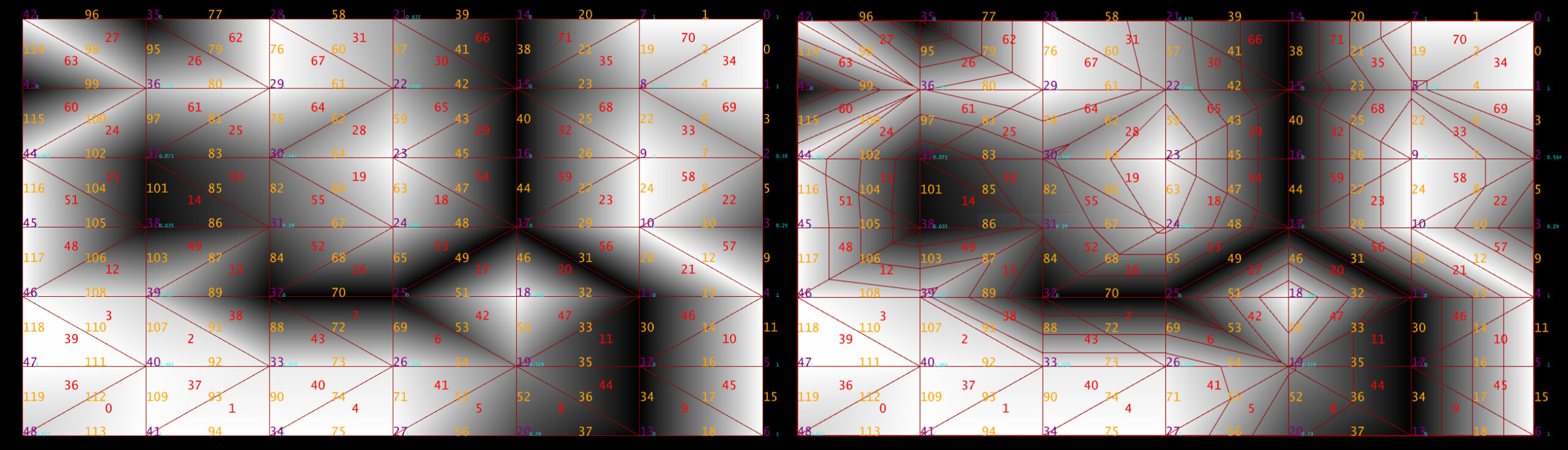
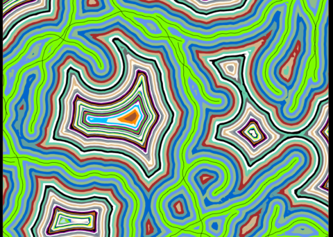
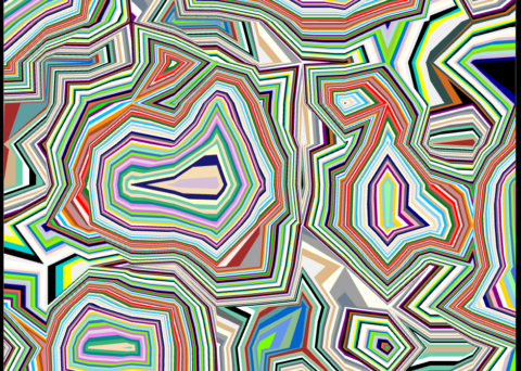
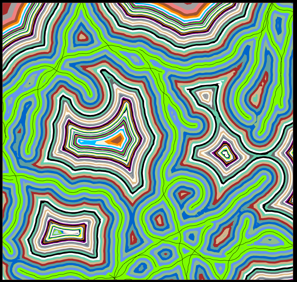
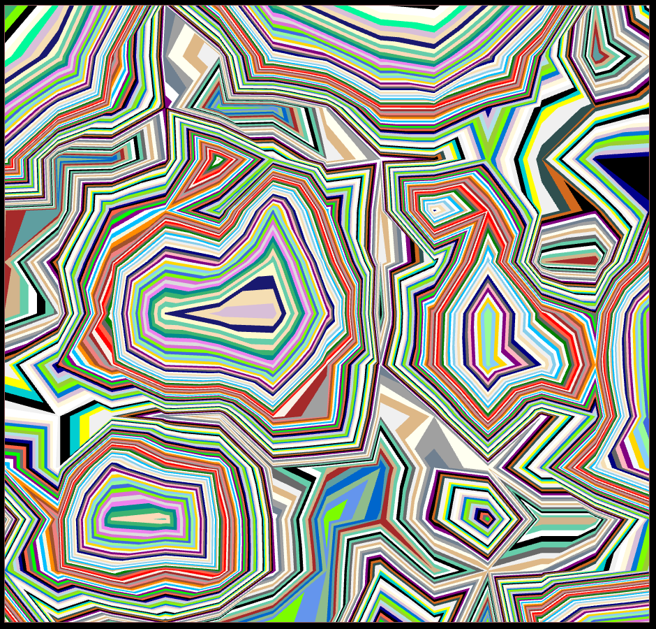
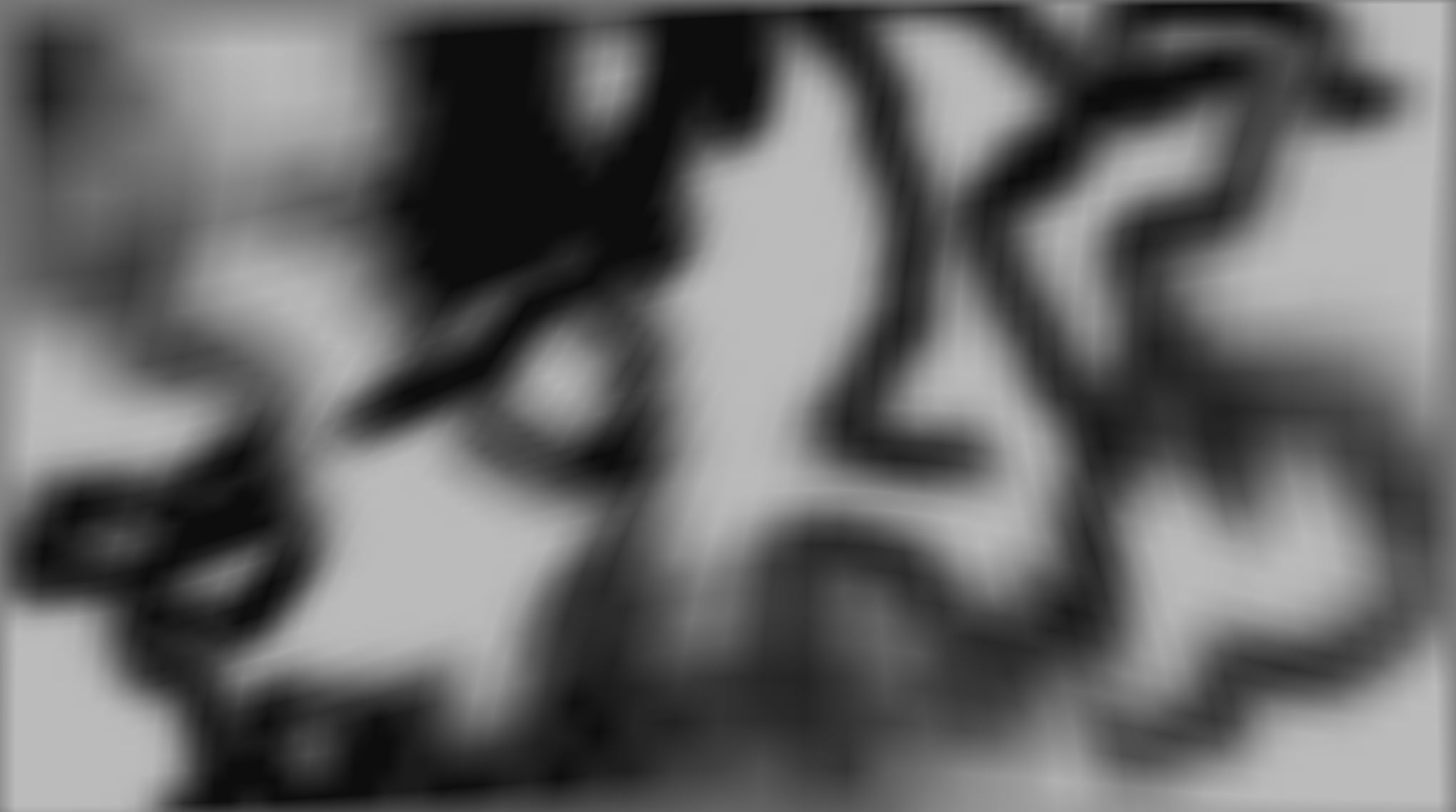
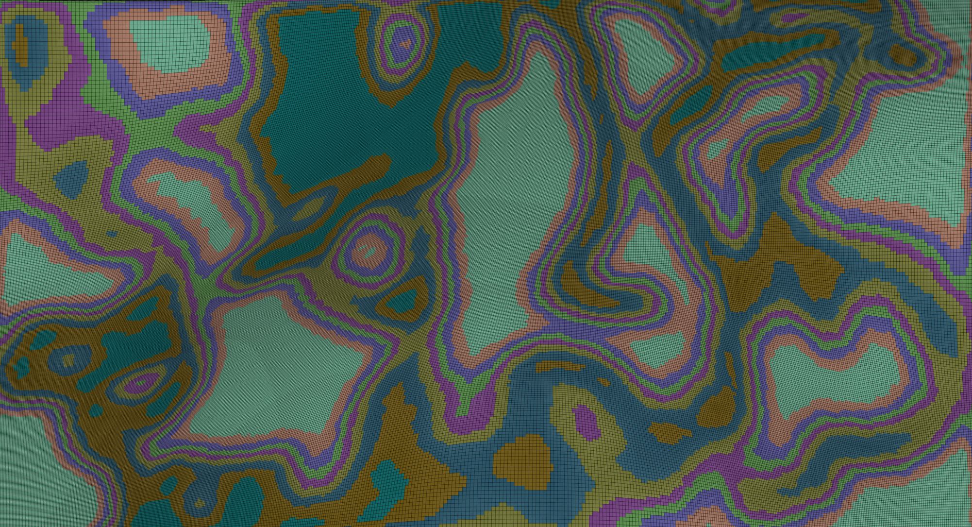
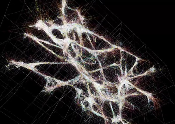
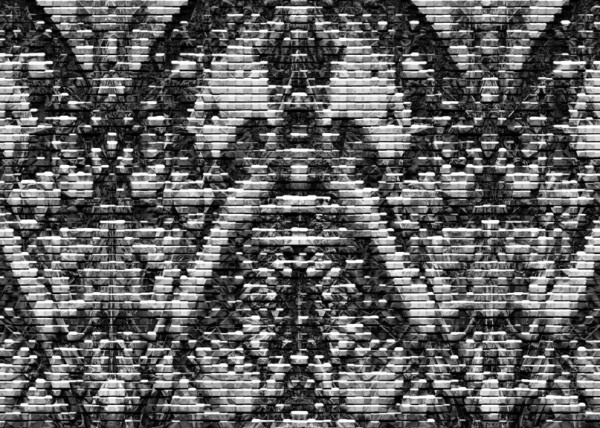
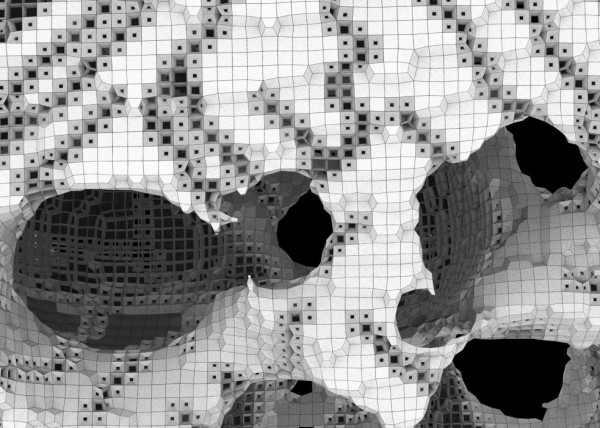
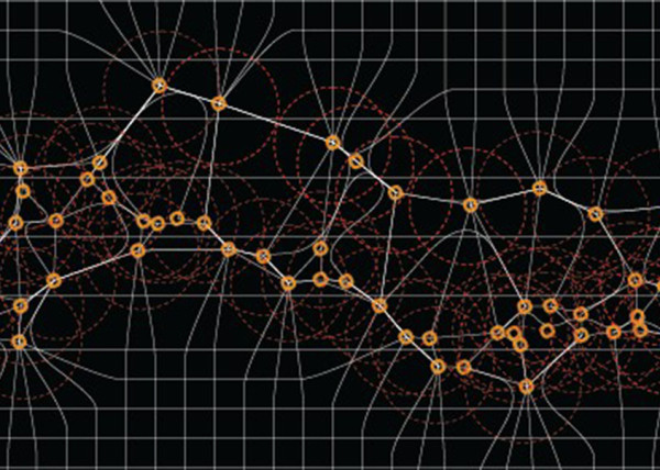
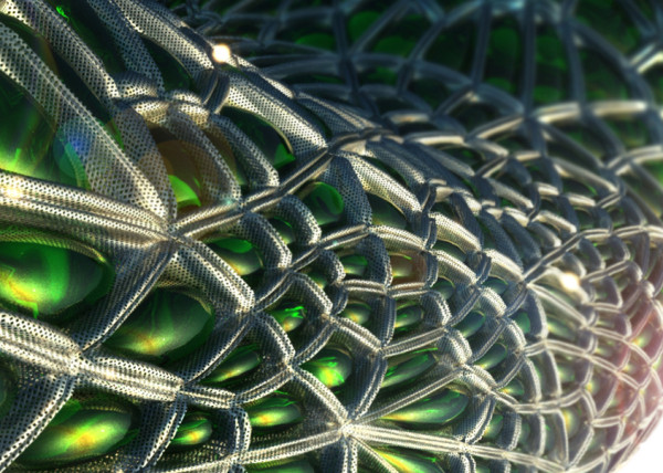
 .DATA STRUCTURES = Left image is raw mesh w. color data vs Remesh based on iso contour values
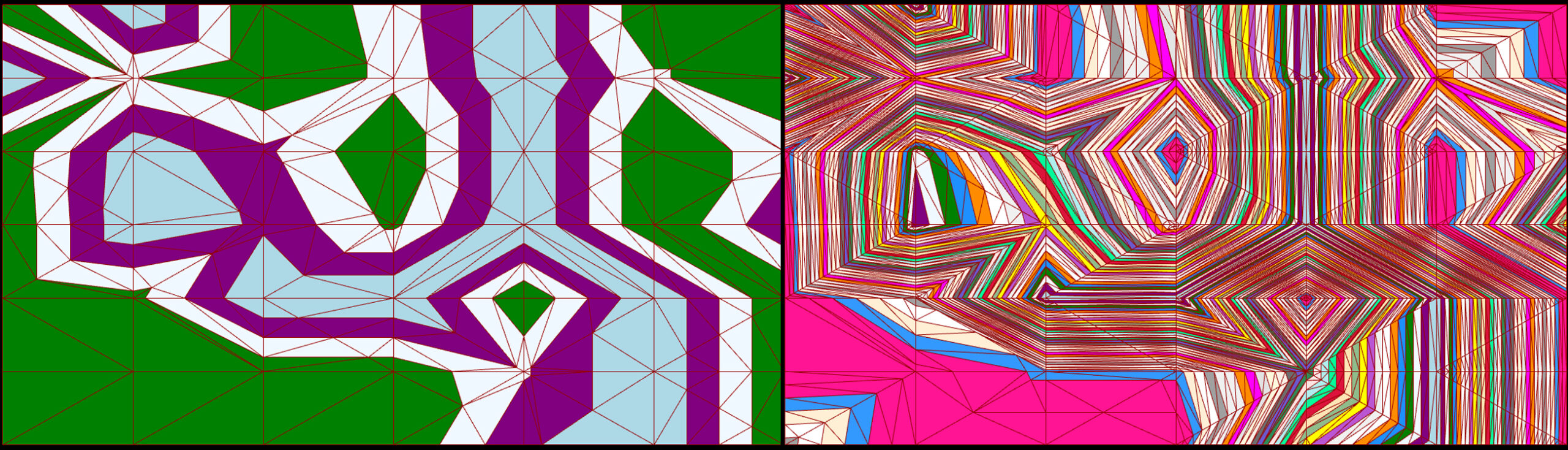
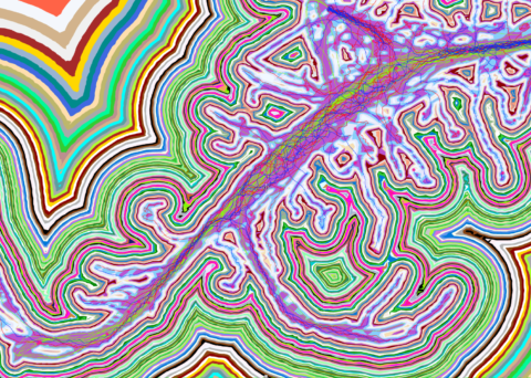
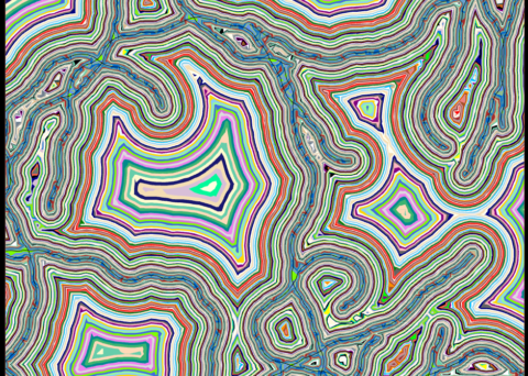
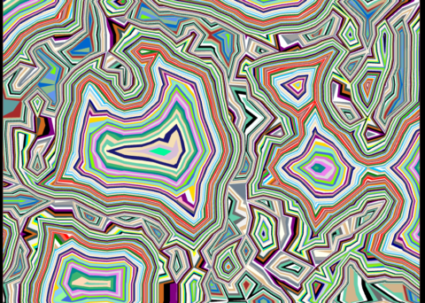
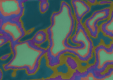
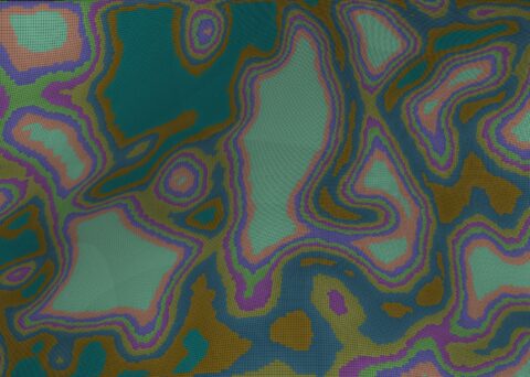
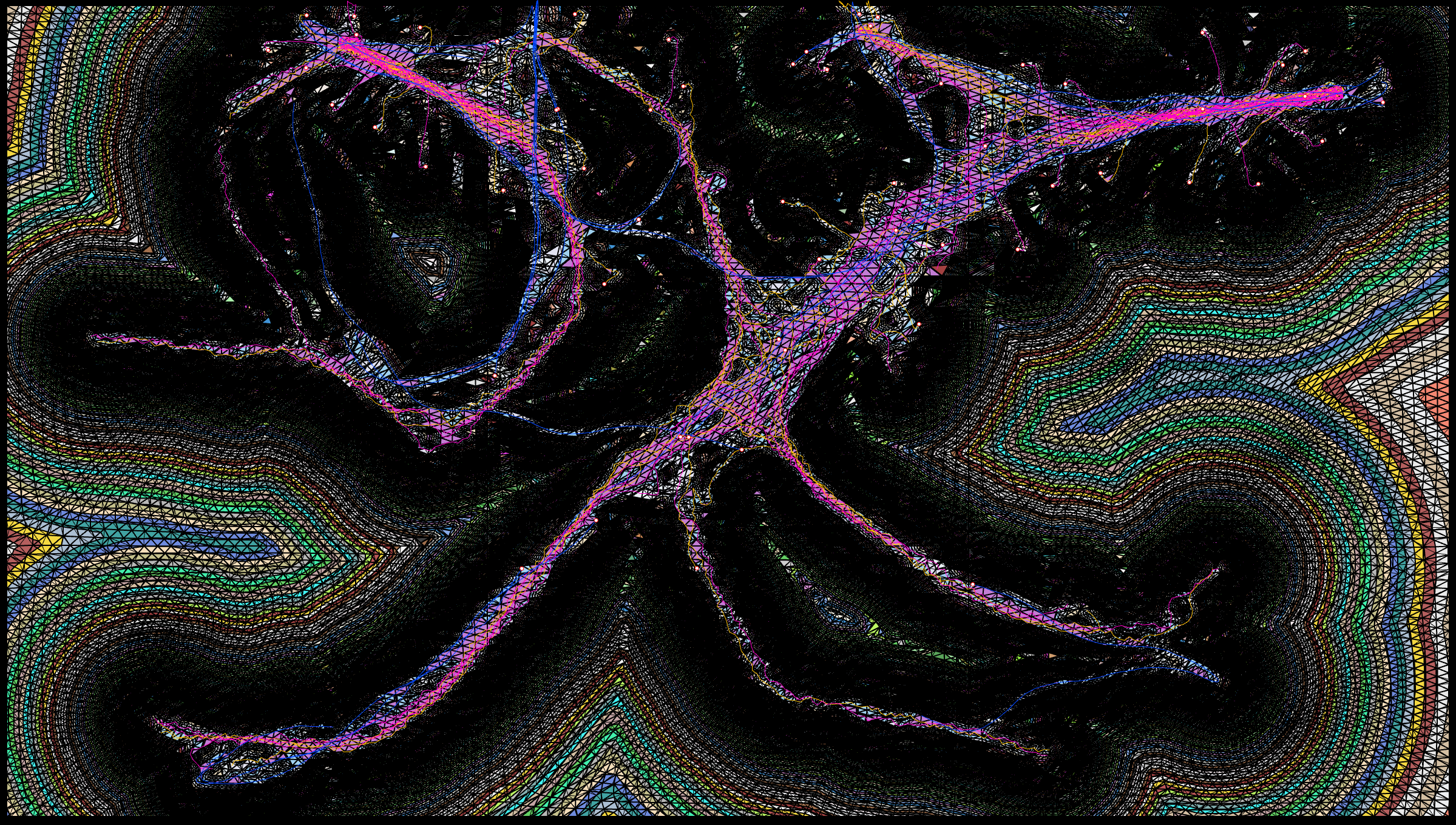
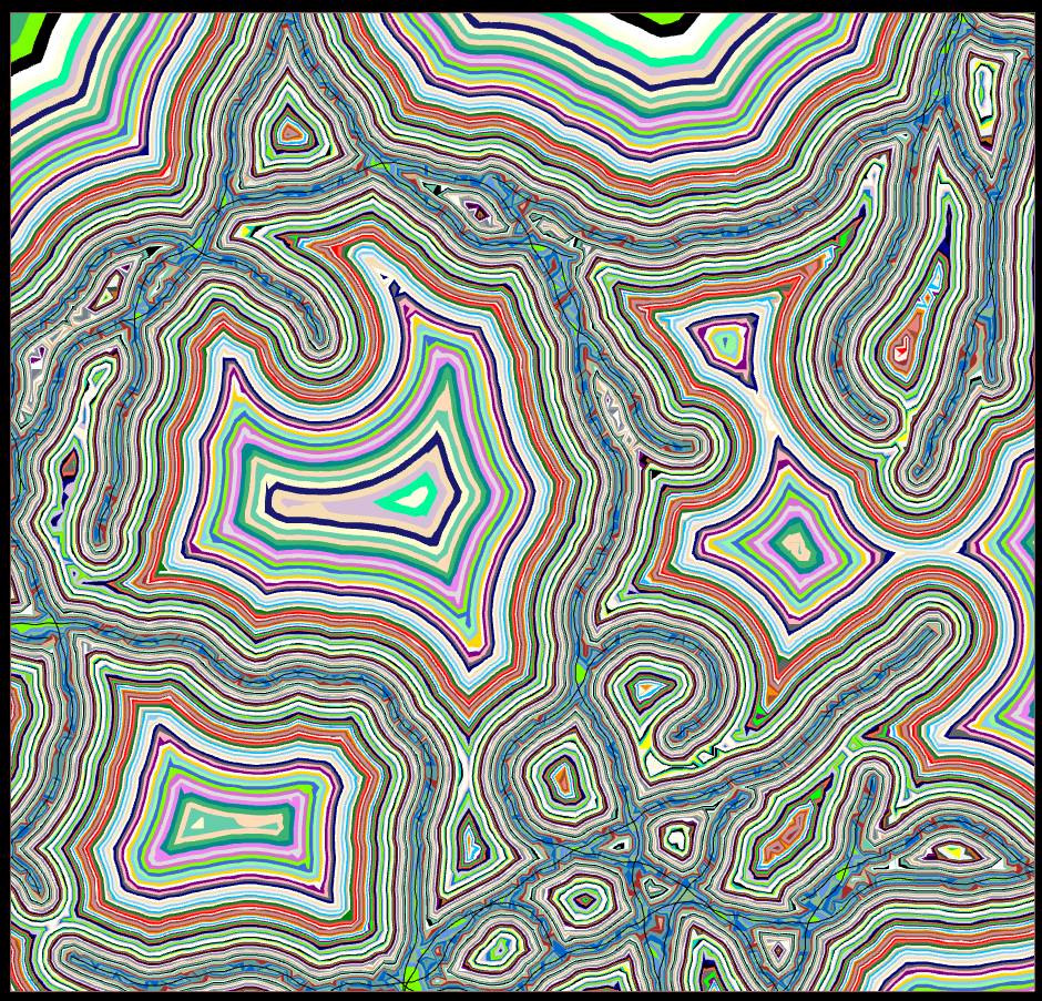
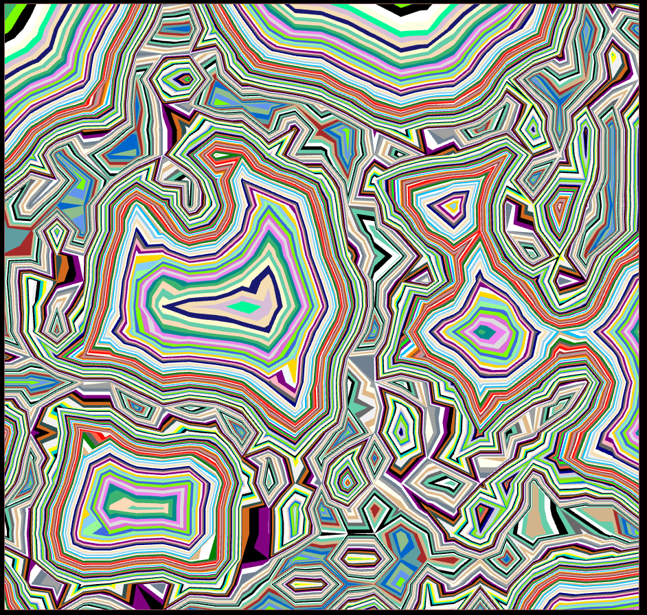
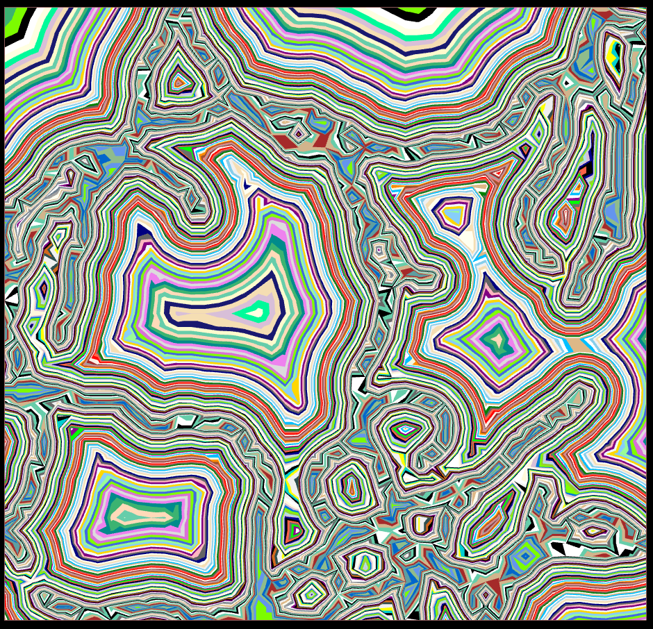
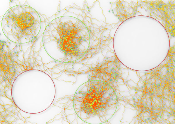
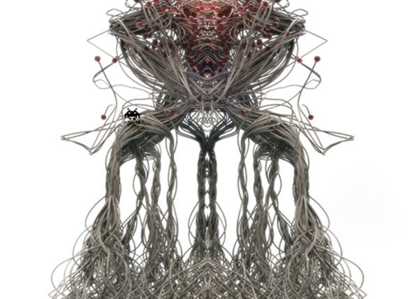
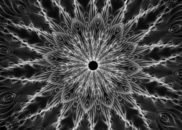
 .EXAMPLE GROUPING SIZE = Same underlying data structure w/ Group Size of 2 vs Group Size of 32
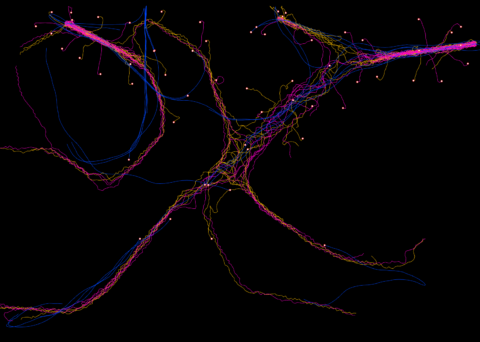
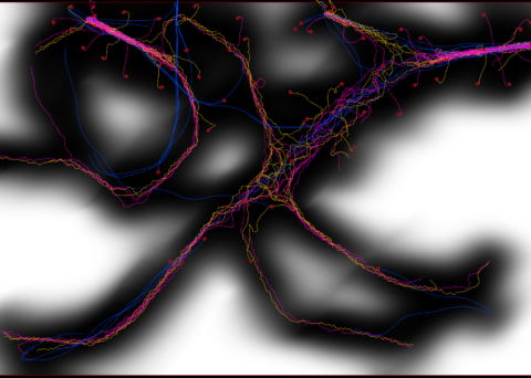
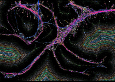

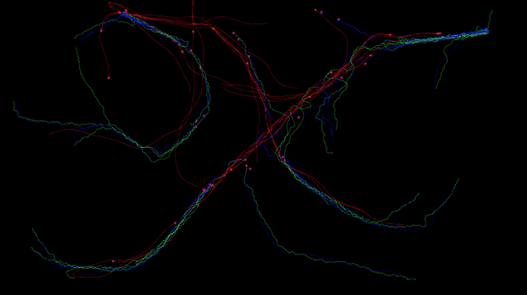
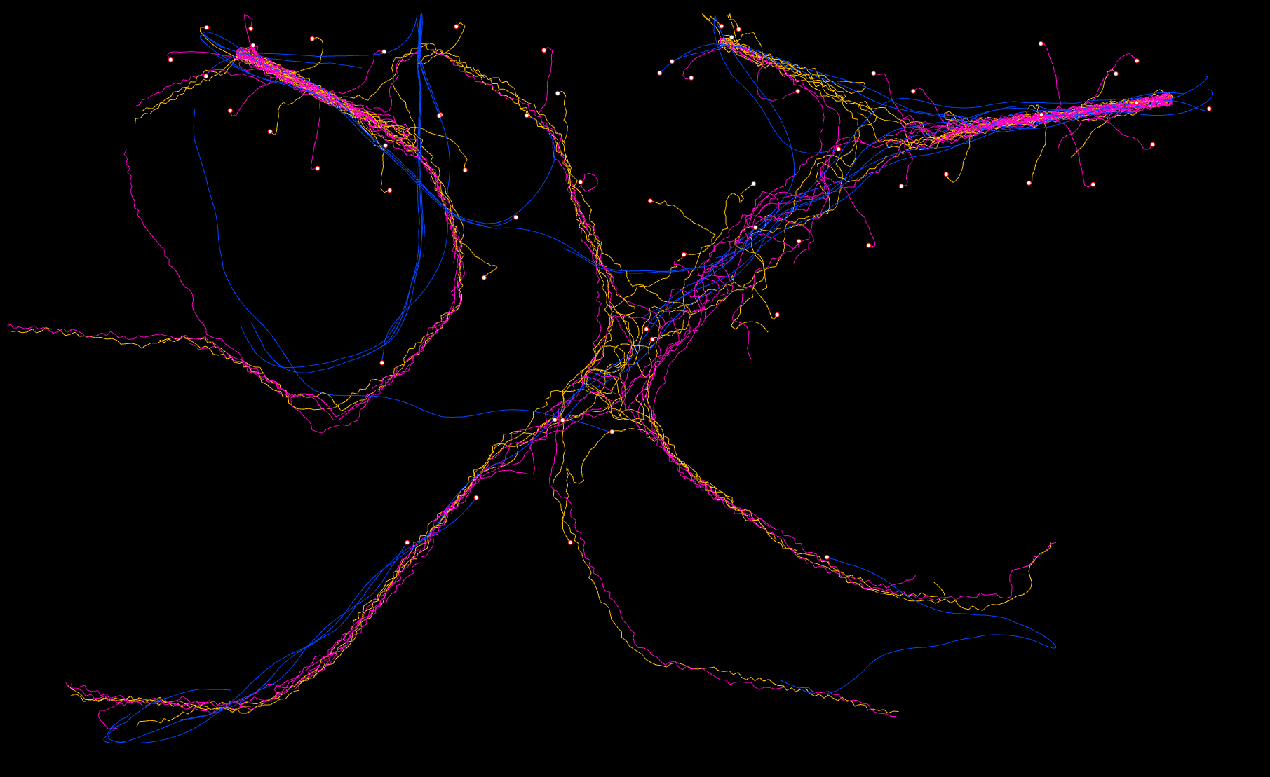
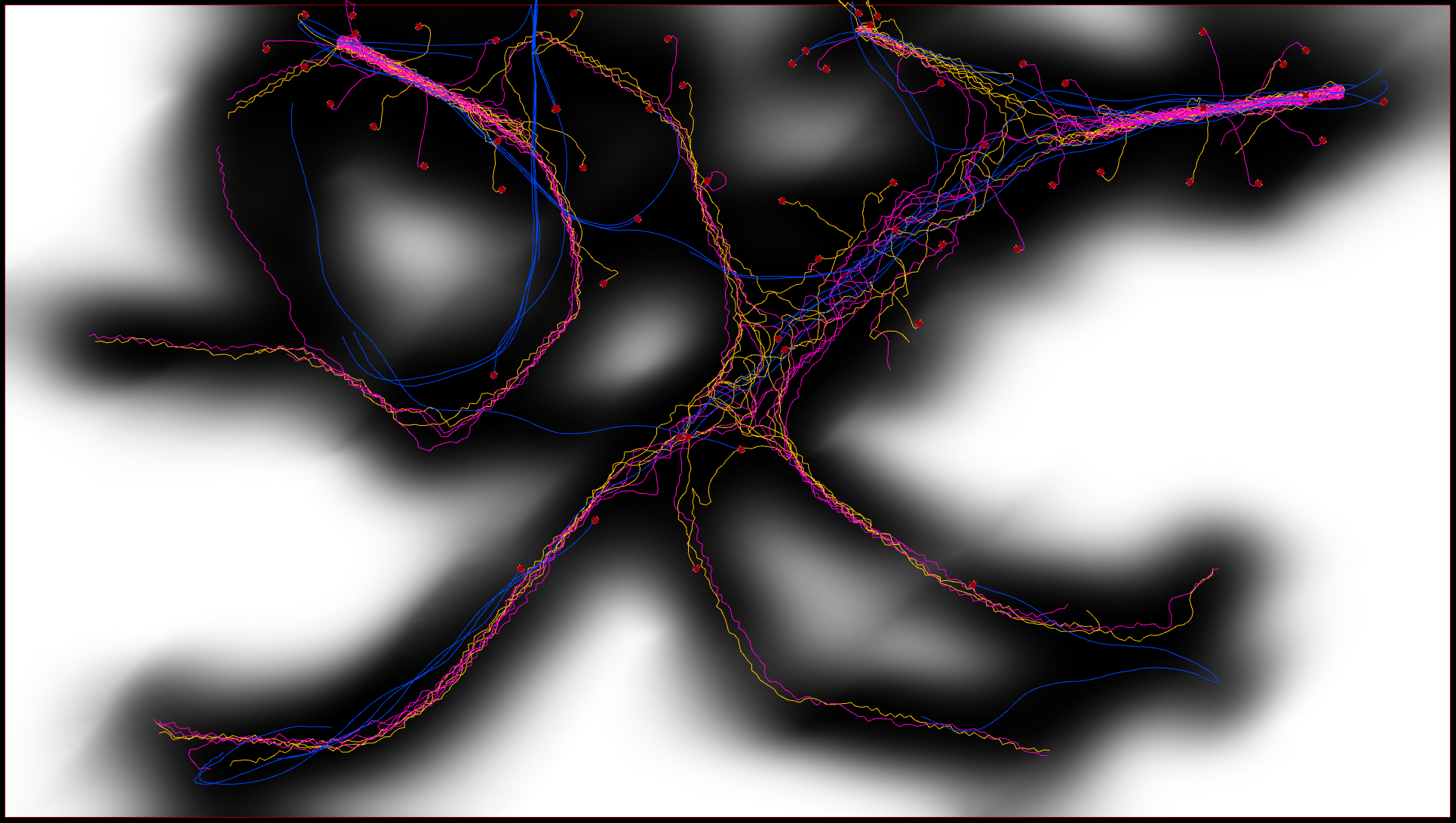
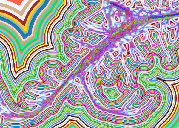
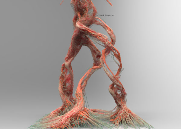
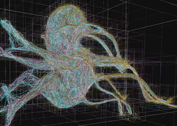
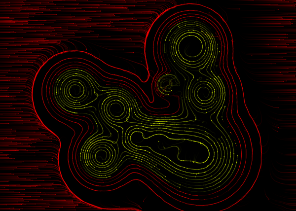
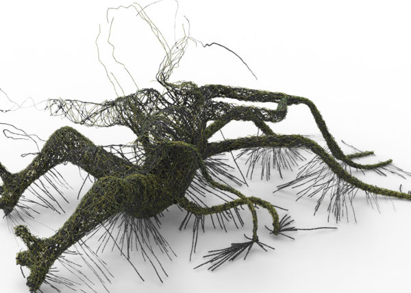
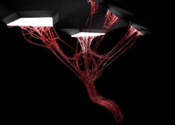
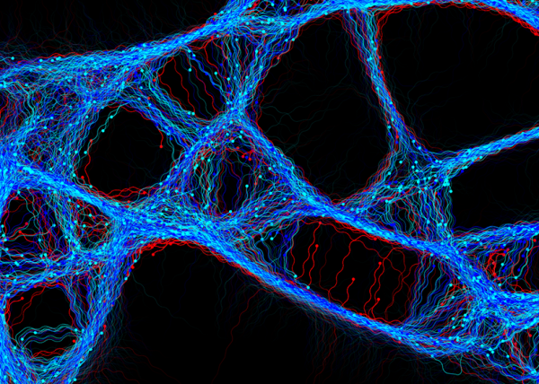
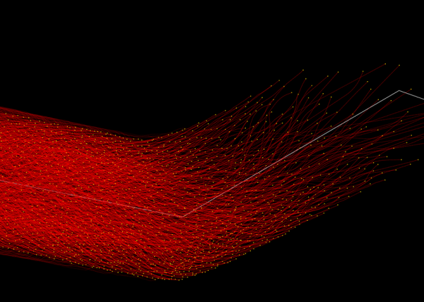
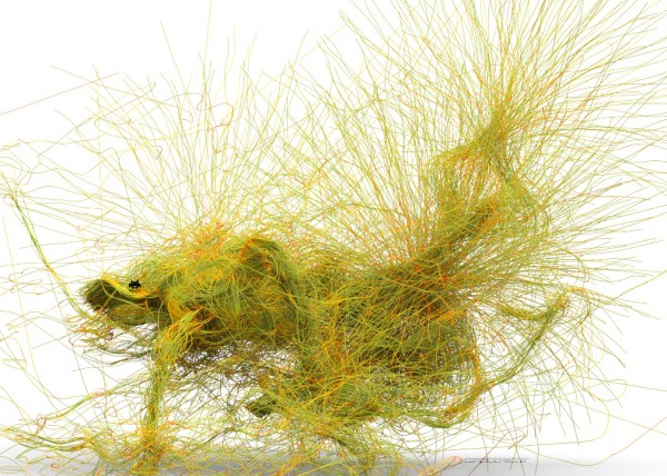
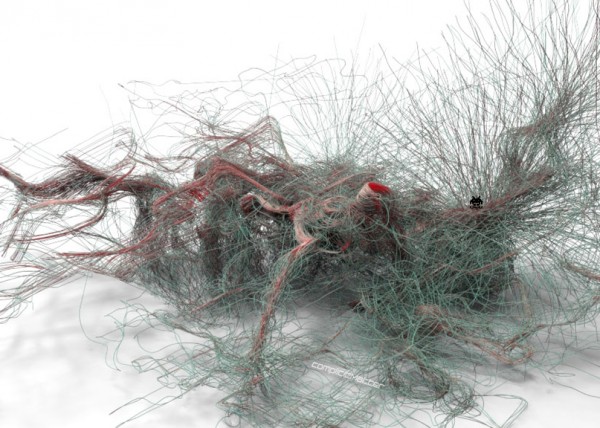
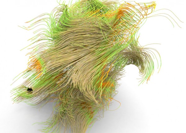
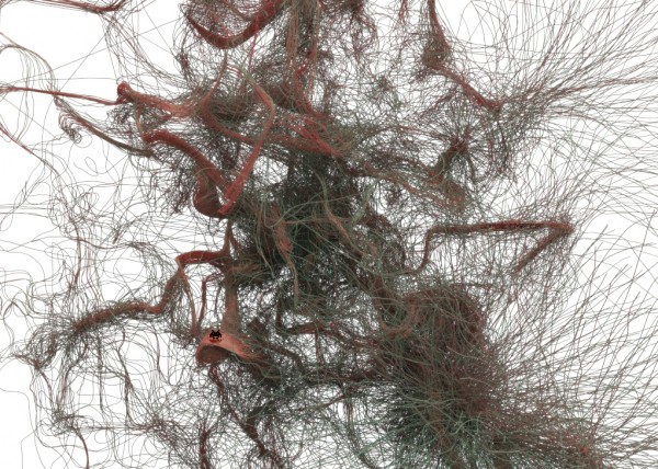
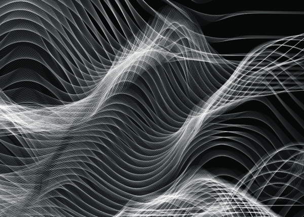
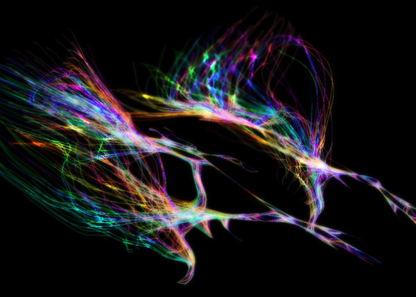
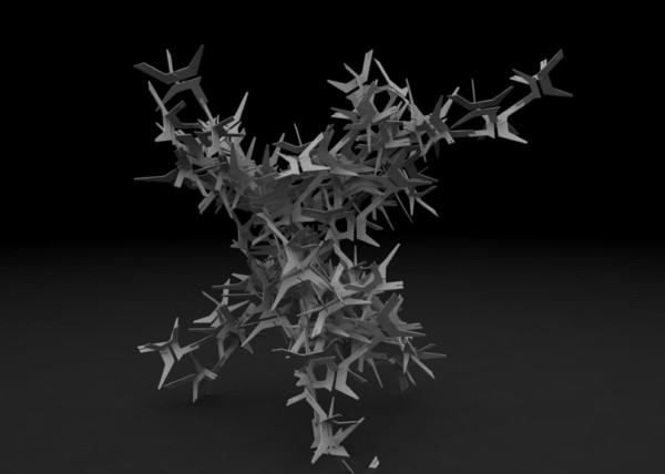
MESHING BY TRAILS & BY POSITION Output changes dramatically when we switch how we want to generate the meshing process, below we see both by agent trails and by agent positions.

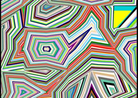
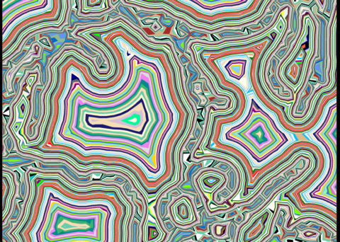
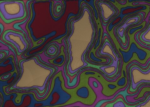
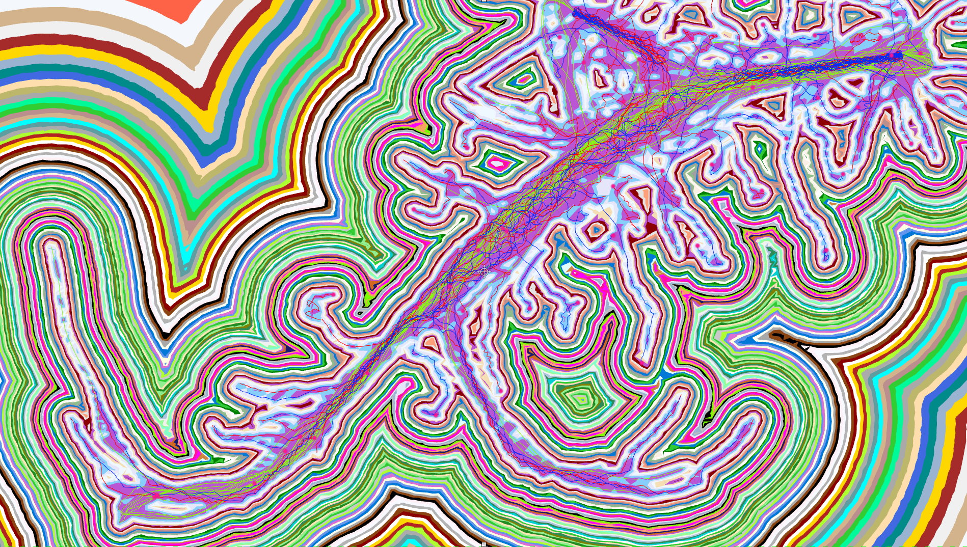
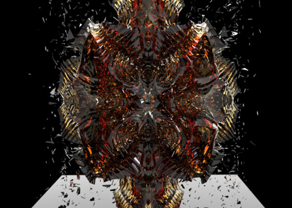
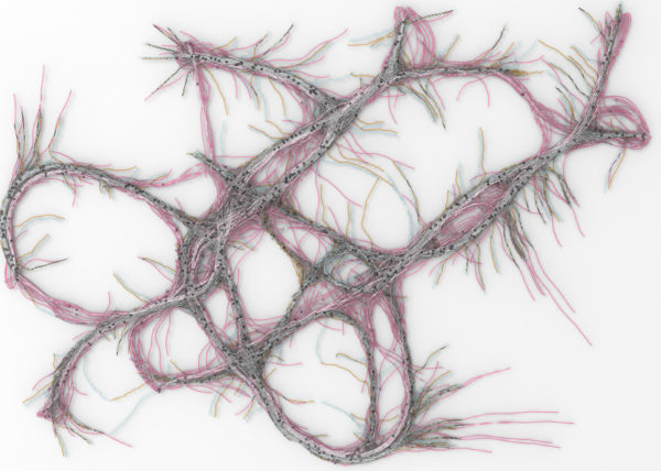
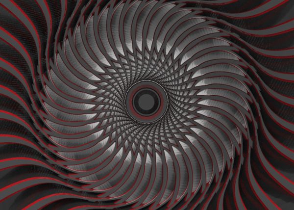
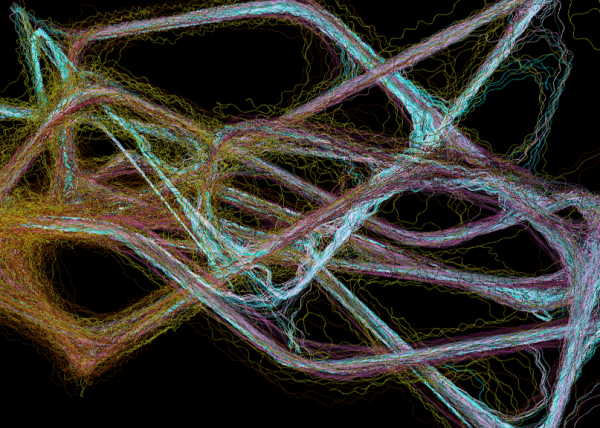
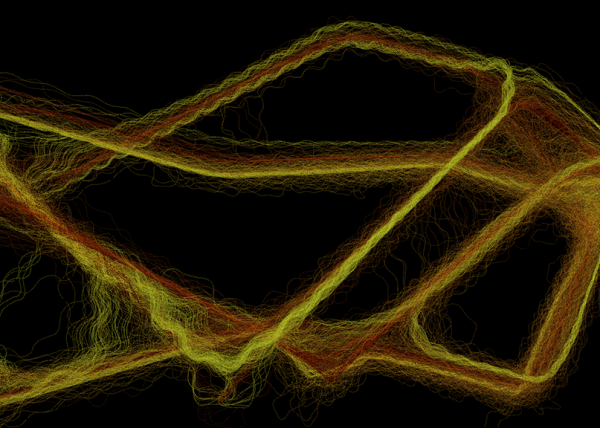
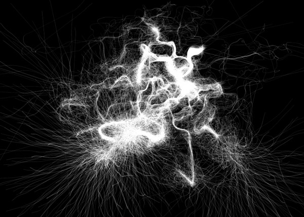
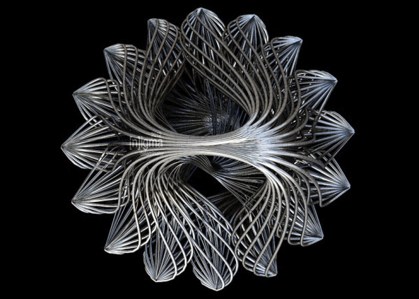
THESHOLD ADJUSTMENTS: We can also begin to get very interesting effects by varying the threshold values as well as the underlying mesh density
ZBRUSH EXAMPLE: As I mentioned earlier ZBrush was a huge inspiration for this process. Below we can see the grouping methods from ZBrush and the output loops
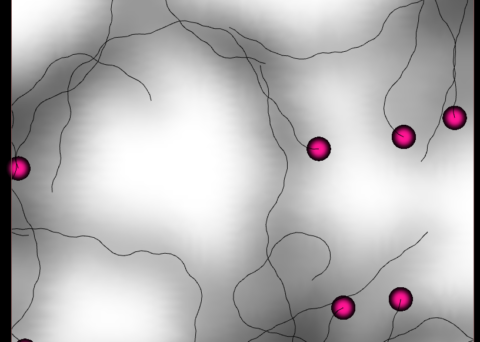
MESHING BASED ON CULEBRA AGENT POSITION INSTEAD OF TRAILS –
Recently in Portfolio
- [K]ernels

- Nike A.I.R Prototypes

- [A]nisochromatic Meshing
- Nike After Dark Tour

- PARAPRAXIS

- [001.HRR] CONCEPT BIKE

- 2040:LUNAR.OUTPOST[a]
- HE.6 2020 Prototype

- CULEBRA.NET
- PYTORCH-CLASSIFIER
- Nike Zoom Superfly Elite

- BENGBU CITY OPERA

- Nike Footscape Flyknit DM

- Jordan Hyperdunk React

- KA-HELMET

- [C]ucarachas
- [S]eeker
- [O]h Baby
- [E]l Papa
- [S]hatter.Brain
- [S]tigmergy
- [F]orces
- CULEBRA.JAVA
- [C]ulebra.MultiBehaviors

- [S]ticky Stuff
- [S]entinels
- [G]allopingTopiary
- RELUXOED

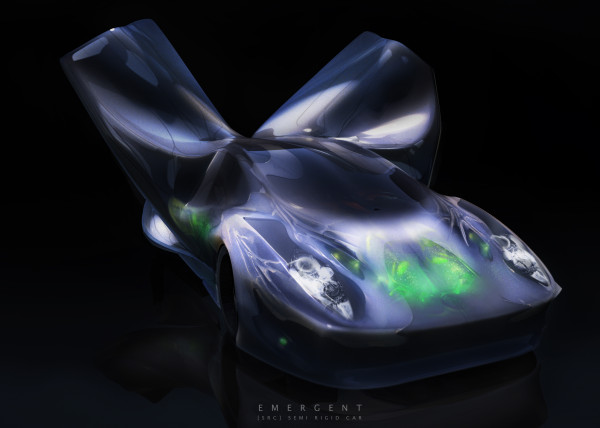
- [SRC] . Semi Rigid Car
- [P]erlin
- [E]ternal Wanderers
- [W]heelie
- [S]labacube

- [M]esh Crawlers
- [L]a Silla
- [3]D BabyMaking Trackstars
- [3]D Trackers
- [2]D BabyMaking Trackers
- [T]rackers
- CULEBRA GRASSHOPPER
- culebra.[M]eshCrawlers.3D
- culebra.[H]ybrid.3D
- culebra.[F]lorgy
- culebra.[F]ockers.3D
- culebra.[F]ockers.2D
- culebra.[N]oisey.3D
- [E]l Nino
- culebra.[S]elfOrg
- [D]rippin

- culebra.[N]oisey.2D

- [C]reepyCrawlers
- [J]eepresesCreepers
- [T]2000
- PUFFER PLEATNESS
- EMERGEN[CY]
- [L]iquified
- [S]uckedComp
- [X]plosion

- MR. EW

- [H]airGoo
- [B]alled

- [n]injaStars
- [b]loomer
- [t]rip city
- TAPE GUNNED

- [B]oom

- [M]iller Time
- [D]elamjam
- [B]rain Zapper
- [B]ig Bird

- [E]gg Tube Pavillion
- [A]llice’s Easter Tree

- [S]weet Honey
- [U]M.Urgent
- [t]oo.urgent
- [B]onnie..+..Clyde
- [B]io Mess
- [EL]Mojado.Virus
- [W]HAT the …!
- [H]ot Lava
- [P]leat Diddy

- [t]erminator easter egg
- Mr. BB
- [B]less You
- [F]antastic + Interactive
- [S]oo_Minimally_Pathed
- [P]uffer Fish.Fab
- [M]an Eater
- [AHH] Alien House Hunters
- [W]eave Machine
- Sportbike Racing

- Grappling

- Kart Racing

Leave a reply